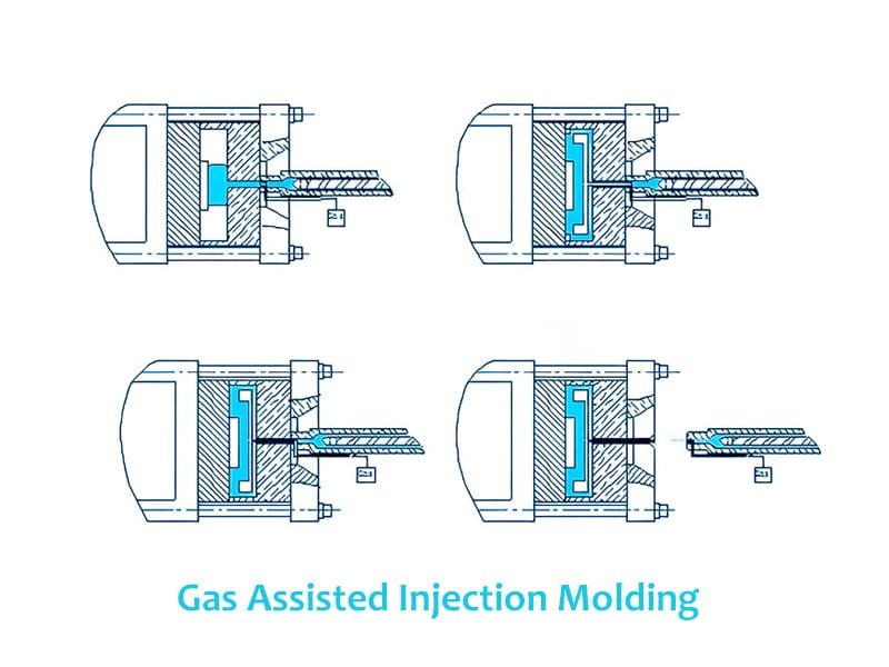
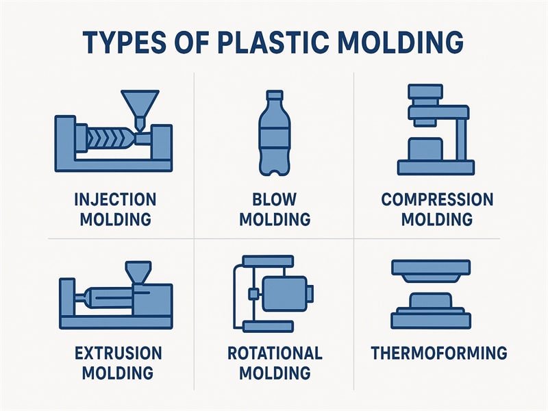
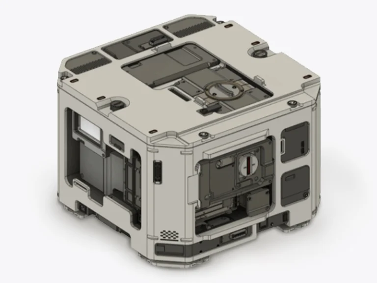
Using injection molding core is one of the key strategies for optimizing injection molded part design. Manufacturers can achieve a more efficient material distribution by strategically incorporating mold cores into the mold design, leading to lighter and more cost-effective parts. Coring is particularly beneficial for large or thick-walled parts, where solid sections would be impractical and expensive. In this post, we will explore what is coring in injection molding, the benefits, the challenges, and the process of core in injection molding process.
What is Coring in Injection Molding?
Coring in injection molding is the process of removing excess material from thick sections of a plastic part to achieve a more uniform wall thickness. This technique involves creating hollow sections or pockets within the part by incorporating cores into the mold desing, resulting in distinct walls and ribs that maintain structural integrity.
A core is a feature within the mold that shapes the internal cavities of the part, effectively removing material from the solid sections.

The Purpose to Injection Molding Core
Core pins injection molding serves several important purposes:
Material Savings: By removing unnecessary mass, coring helps reduce material costs, which is particularly valuable for large parts or high-production runs.
Reduced Cooling Time: Thick areas in molded parts can lead to prolonged cooling times, which can slow down production cycles. Coring helps to short cooling process, allowing for faster cycle times and increased productivity in manufacturing.
Improved Structural Integrity: Coring can be used to balance the weight-to-strength ratio of a part, ensuring it remains structurally sound while not overly dense.
Minimizing Internal Stresses: Thick sections can also introduce internal stresses during the cooling process due to uneven shrinkage. Coring helps alleviate these stresses by promoting more even cooling across the part, thereby reducing the risk of warping or other dimensional issues post-molding.
Injection Molding Core Different Types
There are indeed different approaches to coring in injection molding, each suited to specific design requirements and part geometries. The main types of coring include:
Full-depth coring: This involves creating a hollow section that extends through the entire thickness of a part. Full-depth coring is often used for large, thick sections to significantly reduce material usage and cooling time.
Partial coring: Also known as “blind coring,” this technique creates a hollow section that doesn’t extend through the entire part thickness. It’s useful for maintaining a solid outer surface while reducing internal mass.
Parallel coring: Cores are placed parallel to the mold’s line of draw, which is generally more cost-effective for tool manufacturing.
Angular coring: This can be achieved using angular core pins engaged in sliding mold members, allowing for more complex internal geometries without the need for costly loose details.
Ribbed coring: This combines coring with the addition of ribs to maintain structural strength while reducing material. It’s an effective way to create lightweight yet sturdy parts.
Uniform wall coring: This technique aims to create consistent wall thicknesses throughout the part, which helps prevent issues like sink marks and warping.
Selective coring: This involves removing material only from specific areas of the part where thick sections are problematic, while leaving other areas solid for strength or functionality.
Considerations When Implementing Core in Injection Molding
When implementing coring in part design for injection molding, several key factors need to be considered:
Considerations for Core Placement
Cores should be placed in areas that don’t compromise the part’s overall strength or functionality. Core placement should facilitate smooth material flow during injection, avoiding areas that might impede proper filling. Consider placing cores on non-visible surfaces to avoid potential sink marks or other surface defects. Ensure core-outs don’t interfere with assembly points or mating surfaces.
Optimal Core Orientation
Parallel to the line of draw is the most cost-effective approach for tool manufacturing, as it doesn’t require complex side actions. Cores should be oriented to prevent undercuts that would complicate part ejection. Align cores with the natural contours and features of the part when possible.
Balancing Strength and Material Reduction
Aim for consistent wall thickness throughout the part, including cored areas, to prevent issues like warping and uneven shrinkage. Incorporate ribs in cored areas to maintain structural integrity while reducing material. Typically, rib thickness should be about 50-60% of the adjoining wall thickness. Generally, the depth of a blind hole (core) should not exceed twice its diameter to avoid deflection of the core pin. When transitioning between different wall thicknesses, use gradual changes to minimize stress concentrations. Consider the specific properties of the chosen plastic when determining how much material can be removed without compromising part performance. Utilize mold flow analysis software to optimize core placement and predict potential issues.
Coring Techniques
Based on the search results and the query, here’s an overview of coring techniques in injection molding:
Parallel to the Line of Draw
This is the most common and cost-effective coring technique. Cores are placed parallel to the mold’s opening direction (line of draw). This approach is preferred because it simplifies mold design and manufacturing, and reduces tooling costs. This techniques allows for easier part ejection and minimizes the risk of damage to the mold or part during ejection.
Angular Coring Using Core Pins
This technique involves using angled core pins to create cores that are not parallel to the line of draw. While more complex than parallel coring, it also offers many advantages. It allows for more design flexibility and can create complex internal geometries. It may eliminate the need for side actions in some cases.
Coring with Sliding Mold Members
This method uses sliding or moving parts within the mold to create cores. It’s particularly useful for creating undercuts or complex internal features. It is allowing for cores in directions that would otherwise be impossible with a simple open-and-close mold and enabling more intricate part designs.
Design Guidelines for Effective Core Injection Molding
Here are the design guidelines for effective coring in injection molding:
Wall Thickness Recommendations
Maintain uniform wall thickness throughout the part, including cored areas. Typical wall thickness for injection molded parts should be between 0.060″ to 0.180″. Parts can be molded with walls as thin as 0.020″ and as thick as 1.50″, but extreme thicknesses should be avoided. When transitioning between different wall thicknesses, the change should not exceed 20% of the nominal wall and should transition gradually.
Core Depth Limitations
The depth of a blind hole (core) should generally not exceed twice its diameter to avoid deflection of the core pin. Coring should be employed where possible to eliminate material masses in the part, resulting in more efficient designs and faster production cycle times.
Spacing Between Cores
While specific spacing recommendations aren’t provided in the search results, it’s important to maintain sufficient material between cores to ensure structural integrity and proper material flow.
Draft Angles for Easy Part Removal
A minimum draft angle of 0.5° should be specified on surfaces in the draw of the die. Typical draft is 1°, with more draft aiding in ejection. For openings needed to accommodate features like snaps, a minimum 5° angle is required when formed without using core-pulls (known as a “kiss-off”).
Challenges and Solutions in Coring
When implementing coring in injection molding, several challenges can arise. Here’s an overview of these challenges and their potential solutions:
1. Challenge in potential structural weaknesses:
Coring can potentially reduce the structural integrity of a part if not done carefully.
Solutions:
- Use simulation software to analyze stress distribution and identify potential weak points.
- Implement ribbing in conjunction with coring to maintain strength while reducing material.
- Ensure that core depth does not exceed twice its diameter to avoid core pin deflection.
- Maintain sufficient material between cores to preserve structural integrity.
2.The challenge in ensuring proper mold filling:
Cored sections can create obstacles to material flow, leading to incomplete filling or other defects.
Solutions:
- Design cores parallel to the line of draw when possible, as this facilitates better material flow.
- Use mold flow analysis software to optimize core placement and predict potential filling issues.
- Maintain uniform wall thickness throughout the part, including cored areas, to promote even material flow.
- Consider gate location in relation to cored areas to ensure proper filling.
3.The challenge in balancing cosmetic requirements with functional needs:
Injection Molding Coring can sometimes lead to visible surface defects or compromise the part’s appearance.
Solutions:
- Place cores on non-visible surfaces when possible to avoid cosmetic issues.
- Use gradual transitions between different wall thicknesses to minimize stress concentrations and potential surface defects.
- Consider the use of texturing or other surface treatments to mask potential imperfections caused by coring.
- Balance the depth and placement of cores to achieve the desired material reduction without compromising surface quality.
Conclusion
Injection molding core is a crucial technique that significantly enhances part design and manufacturing efficiency. By strategically removing excess material from thick sections, manufacturers can achieve significant material savings, weight reduction, and improved cooling efficiency. As injection molding technology continues to evolve, coring remains a fundamental technique for producing high-quality, cost-effective plastic parts. Its impact on efficiency, quality, and sustainability makes it an indispensable tool in modern plastic part design and manufacturing.


