Injection molding ejector pins are important part of injection mold. In the Injection Molding process, the ejector pins are responsible for efficiently and reliably ejecting molded parts from the mold cavity. Ejector pin has facilitated the automation of the injection molding process, improved production speed, and ensured more efficient products. In this post, we will introduce how injection molding ejector pin works and how to choose the right ejector pin in the injection molding process.
What Are Injection Molding Ejector Pins?
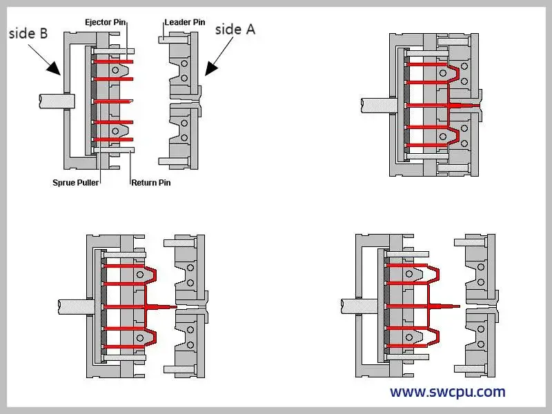
Ejector pins are slim metal rods in injection molds that act like precision pushers. After molten plastic fills the mold’s two halves – the A-side (outer shape) and B-side (inner details) – the cooled part often sticks to the B-side when the mold opens. That’s when these pins spring into action: mounted on the B-side, they gently nudge the finished piece out of the mold. Though only 3-8mm thick (about pencil-lead width), they leave tiny circular marks where they push – like a mold’s “fingerprint.”
Engineers strategically place these pins (sometimes dozens per mold) to avoid damaging delicate parts during ejection. While hidden in plain sight, they’re unsung heroes – without them, your phone case, toy parts, or bottle caps would never cleanly pop out of their molds!

How Does an Injection Molding Ejector Pins Work?
Ejector pins injection molding are small but essential components in the injection molding process. Their job is simple but critical: to push the molded plastic part out of the mold once it has cooled and solidified. Here’s a breakdown of how they work:
How Ejector Pins Work in Injection Molding:
- Molding the Part
First, molten plastic is injected into the mold cavity under high pressure. Once the part is shaped and cooled, it solidifies inside the mold. - Mold Opens
The mold opens, separating the core (where the ejector pins are located) and the cavity sides. The molded part usually stays on the core side due to shrinkage or mechanical features. - Ejection Begins
After the mold opens, the ejector system is activated—typically powered by hydraulic or mechanical force. - Pins Push the Part Out
The ejector pins (also called knockout pins) move forward and push the part off the core. They’re usually arranged strategically to apply even pressure and avoid damaging the part. - Pins Retract
Once the part is released, the pins retract to their original position, ready for the next cycle
- How Does Injection Molding Ejector Pins Work
Key Design Considerations for Ejector Pins:
- Placement: Poor pin placement can cause part deformation or visible marks.
- Size & Shape: Must match the part geometry and required ejection force.
- Material: Usually made of hardened steel for durability.
- Pin Marks: Always a consideration—designers aim to place pins in non-cosmetic or hidden areas.
8 Types of Ejector Pins in Injection Molding
There are several types of ejector pin in mould, each suitable for different temperature ranges and applications:
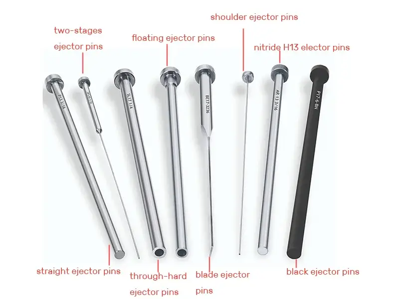
1. Through-Hard Ejector Pins
Materials and Processes:
- H13 (hot work tool steel) or D2 (high carbon, high chromium cold work steel) steel, vacuum heat treated to a full cross-section hardness of 50-60 HRC.
- H13 has excellent resistance to high temperatures (working temperatures up to 600°C), D2 is more resistant to abrasion, but less tough.
Design Features:
- Gradient-free hardness structure to avoid sudden drops in performance due to surface wear.
- Surface roughness Ra ≤ 0.4 μm reduces friction coefficient with the die.
Typical Applications:
- Long-term mass production (>500,000 die cycles) of abrasive materials such as glass fiber reinforced nylon (PA+30%GF).
- Scenarios in automotive lampshade molds that are subject to frequent high-pressure ejection.
2. Nitrided H13 Ejector Pins (Nitrided H13 Ejector Pins)
Surface Treatment:
- Ion nitriding process, forming a 50-80μm nitrided layer on the surface, with a surface hardness of 1100-1200HV (≈70 HRC).
- The core maintains the original hardness of H13 (48-52 HRC), realizing the characteristic of “rigid outside and tough inside”.
Advantages:
- 3 times higher chemical resistance, suitable for processing of halogen-containing materials such as PVC.
- High-temperature red hardness: maintains high surface hardness even under 400°C environment.
Application Examples:
- Laptop shell mold (material: PC/ABS), ejector temperature up to 160-180°C.
- Medical device molds that require steam sterilization.
3. Black Oxide Ejector Pins
Coating Characteristics:
- Blackening process generates Fe3O4 film layer with a thickness of 1-1.5 μm, which reduces the coefficient of friction by 15-20%.
- The oil content of the surface can be 0.5-1mg/cm², realizing self-lubrication effect.
Economic Analysis:
- Cost is only 1/3 of nitrided ejector pins, suitable for trial molding stage (typical service life is about 50,000-100,000 times).
Restrictions on use:
- Acidic environments (e.g. POM material releasing formic acid) are prohibited to prevent rapid corrosion of the film layer.
4. Straight Ejector Pins (Straight Ejector Pins)
Standardized Parameters:
- Diameter range: Φ1.0mm-Φ20mm (in 0.5mm increments), length tolerance h6 level (±0.013mm).
- Chamfering specifications: head 15° × 0.3mm, tail 45° × 0.5mm standard configuration.
Failure Mode:
- Common bending failure occurs when L/D ratio > 8:1, need to be used with ejector plate guide sleeve.
Innovative Design:
- Stepped straight ejector pins: Multiple diameters on the same ejector pin, combining stiffness and weight reduction requirements.
5. Shouldered Ejector Pins
Structural Mechanics:
- The difference in step diameters is usually 0.5-2mm, forming a mechanical stop that can withstand impact stresses of 300-500N/mm².
- The head transition fillet R0.3-R0.5 avoids fracture due to stress concentration.
Precision fit:
- The gap between the step surface and the formwork is ≤ 0.02 mm, preventing the plastic melt from penetrating and creating “flying edges”.
Special Variants:
- Double-step ejector: for precision ejection of ultra-thin products (e.g. cell phone film, thickness 0.2 mm).
6. Blade Ejector Pins
Cross-section Optimization:
- Rectangular cross-section with a width-to-thickness ratio of 2:1 to 5:1 (common sizes: 2 x 1mm to 15 x 3mm).
- Trapezoidal cross-section design increases flexural rigidity by 15% for deep cavity ejection (e.g. lipstick tube molds).
Surface Finish:
- Mirror polished (Ra ≤ 0.1μm) with TD finish (vanadium carbide coating) for ejection of transparent parts.
Innovative Application:
- Flat ejector pin with air circuit: internal Φ0.3mm micro-perforations are integrated to synchronize ejection with air-assisted molding.
7. Floating Ejector Pins
Movement Mechanism:
- Spring pre-compression design: typically compresses 3-5mm to provide 20-50N reset force.
- Ball self-adjusting structure: allows ±2° deflection compensation, suitable for use with tilt top mechanism.
Dynamic Analysis:
- Response time <0.1s, can adapt to the high-speed molding rhythm of 300 times/hour.
Typical Configuration:
- In the automobile bumper mold, it is linked with the slanting top + slider mechanism to compensate for the closing error of 0.2-0.5mm.
8. Two-Stage Ejector Pins
Timing Control:
- The first stage ejector stroke accounts for 60-70%, and the second stage is started after a delay of 0.5-1.5 seconds.
- Adopt double oil circuit control or mechanical ratchet mechanism to realize action separation.
Mechanical Simulation:
- Reduces peak ejection stresses by 40% for brittle materials such as liquid crystal polymers (LCP).
Complex Applications:
- Automotive connector molds: first eject 0.5mm to break vacuum adsorption, then complete ejection.