Factors Influencing the Formation of Weld Lines and Knit Lines
The appearance and severity of weld lines and knit lines in injection molding depend on several factors related to material properties, processing conditions, and mold design. Understanding these influences is crucial for effective injection molding troubleshooting and defect prevention.
1. Material Properties
Different plastics behave differently when subjected to heat and pressure.
- Viscosity and Flowability: High-viscosity materials, such as polycarbonate (PC) or nylon (PA), are more prone to weld and knit lines because they resist flow and may not merge properly at meeting points. In contrast, low-viscosity materials like polypropylene (PP) or polyethylene (PE) flow more easily and can form stronger bonds.
- Fiber-Reinforced Composites: In injection molding fiber-reinforced plastics, knit lines are especially problematic because fibers do not align properly at the flow fronts, weakening the material’s structural integrity.
- Additives and Fillers: The presence of flame retardants, pigments, or glass fibers can impact material flow and bonding, increasing the likelihood of defects.
2. Injection Molding Process Parameters
Adjusting process parameters can significantly reduce the occurrence of weld lines and knit lines in plastic injection molding.
- Injection Speed and Pressure: Insufficient pressure can lead to weak bonding where flow fronts meet, while excessive speed may cause turbulence, increasing defect visibility. Optimizing these parameters helps prevent knit lines injection molding by ensuring smooth and even flow.
- Melt Temperature: If the plastic cools too soon, weld lines become more pronounced. Higher melt temperatures improve bonding but require careful control to avoid degradation.
- Packing and Holding Pressure: Proper holding pressure allows molten material to fill gaps and eliminate weak spots, improving weld line prevention.
3. Mold Design and Gating Strategy
Poor mold design is a leading cause of injection molding defects, including weld and knit lines.
- Gate Placement: Multiple gates can create weld lines where the separate flows meet. Strategic gate positioning can direct material flow to avoid critical areas.
- Wall Thickness Variations: Uneven cooling occurs when some sections of the part cool faster than others, increasing the risk of knit line formation. Uniform wall thickness minimizes this problem.
- Venting and Cooling System: Inadequate venting traps air at the flow front, preventing proper fusion. Proper vent design and cooling channel placement help regulate material flow and reduce injection molding defects.
4. Part Geometry and Flow Path
The shape and design of the molded part influence where weld and knit lines develop.
- Sharp Corners and Thin Sections: These areas experience rapid cooling, making them hotspots for knit lines. Smoother transitions in design improve material flow.
- Complex Features and Inserts: Molded parts with ribs, bosses, or metal inserts create obstacles in material flow, increasing the likelihood of weld lines. Optimizing the part design can minimize injection molding defects.
Solutions for Weld Line and Knit Line Defects
Eliminating or minimizing weld lines and knit lines in plastic injection molding requires a combination of process optimization, mold design improvements, and material selection. Each defect requires a slightly different approach, as their formation mechanisms differ. Below are practical strategies to enhance weld line prevention and knit line prevention for high-quality molded parts.
1. Optimizing Injection Molding Parameters
Increase Melt Temperature and Mold Temperature
- A higher melt temperature enhances polymer chain mobility, allowing flow fronts to fuse properly. For semi-crystalline materials (e.g., nylon, PBT), increasing melt temperature ensures better molecular diffusion, leading to stronger weld lines.
- Raising mold temperature prevents premature cooling, reducing knit line weakness. For example, PC-ABS blends require mold temperatures above 80°C (176°F) to ensure proper bonding.
Optimize Injection Speed and Pressure
- A higher injection speed reduces cooling before flow fronts meet, improving weld line integrity. However, excessive speed can introduce air traps or jetting defects.
- Packing pressure should be fine-tuned to push material into weak areas, eliminating air pockets at weld lines. For fiber-reinforced plastics, moderate holding pressure prevents fibers from misaligning at the weld interface.
Adjust Holding and Packing Time
- Longer holding time compensates for shrinkage and allows polymer chains to rearrange, improving mechanical strength at weld lines.
- Proper gate sealing timing ensures continuous material feeding, reducing voids at knit lines.
2. Enhancing Mold Design for Better Flow Merging
Optimize Gate and Runner Placement
- Position gates to avoid direct flow splits in high-stress areas. For example, in automotive bumper molding, placing gates along the longest flow path ensures gradual merging, minimizing visible weld lines.
- Use a hot runner system instead of a cold runner, maintaining consistent melt flow to reduce weld line formation.
Increase Venting and Gas Escape Paths
- Inadequate venting traps air at weld line formation points, preventing proper fusion.
- Adding micro-venting (0.02–0.05 mm vents) near weld-prone areas allows gases to escape, improving bonding.
Modify Cooling System Design
- Uniform cooling prevents localized knit line formation.
- Using conformal cooling (e.g., 3D-printed cooling channels) ensures even heat dissipation, reducing premature flow solidification.
3. Selecting the Right Material for Improved Weld and Knit Line Strength
Use Low-Viscosity Resins for Better Flowability
- Low-viscosity grades of polycarbonate (PC), polypropylene (PP), or polyethylene (PE) flow better and reduce weld line weakness.
- For glass-filled materials, a lower viscosity matrix prevents fiber misalignment at weld lines.
Modify Additives and Reinforcements
- Increasing impact modifiers (e.g., rubberized ABS) enhances fusion at weld lines, improving part durability.
- Reducing fiber content minimizes discontinuities at knit line regions, preserving structural integrity.
Consider Self-Healing or Chemical Additives
- Certain thermoplastic elastomers (TPEs) and reactive polymer modifiers enhance chain entanglement at weld lines.
- Ultrasonic energy or infrared heat treatments can be applied post-molding to strengthen weak knit lines.
4. Adjusting Part Design to Improve Flow
Smooth Out Sharp Corners and Complex Features
- Sharp flow transitions create flow hesitations, leading to knit line defects. Using fillets and rounded edges ensures a continuous melt front, preventing unwanted weld line formation.
Increase Wall Thickness in Critical Areas
- Thin-walled parts cool faster, exacerbating knit lines. For example, increasing wall thickness from 1.5 mm to 2.5 mm in laptop housings has been shown to improve weld line strength by 30%.
Redesign Features to Avoid Flow Splits
- Relocating bosses, ribs, and inserts away from flow intersection points prevents weak weld lines.
- Using flow simulation software (e.g., Moldflow, Sigmasoft) helps optimize part geometry to eliminate injection molding defects.
5. Post-Processing Methods to Strengthen Weak Areas
Annealing and Heat Treatment
- Controlled post-molding heating (90–130°C for 30 minutes) allows polymer chains to relax and fuse better, improving weld strength.
- For fiber-reinforced composites, annealing reduces fiber misalignment at weld and knit lines.
Surface Coatings and Texturing
- Laser texturing or chemical etching can mask visible weld line defects, improving aesthetics.
- Clear coatings or UV-cured resins can enhance surface uniformity while strengthening knit line areas.
Conclusion
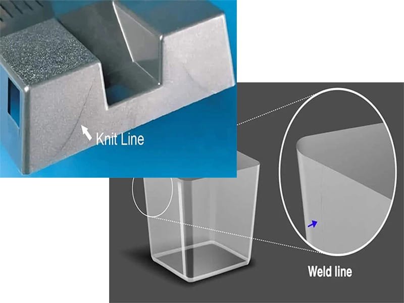
The key difference between weld lines and knit lines lies in their formation. Weld lines occur when molten plastic from different gates or runners meets but fails to bond fully, leaving visible seams. Knit lines, on the other hand, result from incomplete molecular bonding, often due to variations in cooling rates or uneven flow paths. Recognizing these distinctions is essential for improving molded part quality and durability.
Manufacturers can proactively address these defects by optimizing mold design, refining injection parameters, and selecting suitable materials. These improvements not only enhance the visual appeal of molded parts but also ensure they meet performance standards, leading to higher-quality, more reliable products in the market.