Correctly plastic part design guideline is crucial for ensuring durability, functionality, and manufacturability. Proper plastic part design can lead to reduced production costs, improved product performance, and fewer defects. This post aims to provide comprehensive insights into the key considerations for effective plastic part design for injection molding, helping designers and engineers create high-quality, reliable products.
1. Wall Thickness Considerations
One of the fundamental principles in plastic part design is maintaining uniform wall thickness. Maintaining uniform wall thickness is the fundamental principle in plastic part design. Wall thickness is a critical factor in plastic parts design that significantly impacts the part’s strength, manufacturability, and overall quality. plastic part design guideline :Maintaining uniform wall thickness is the fundamental principle in plastic part design.
Uniform wall thickness ensures consistent cooling and shrinkage, reducing the risk of warping, sink marks, and internal stresses. It promotes even material flow during injection molding, preventing issues like short shots or air traps. The consistent thickness helps maintain the dimensional stability and structural integrity of the part.
Techniques for Maintaining Consistent Thickness:
- Use a wall thickness ratio of 1: (1.5-2) for adjacent parts.
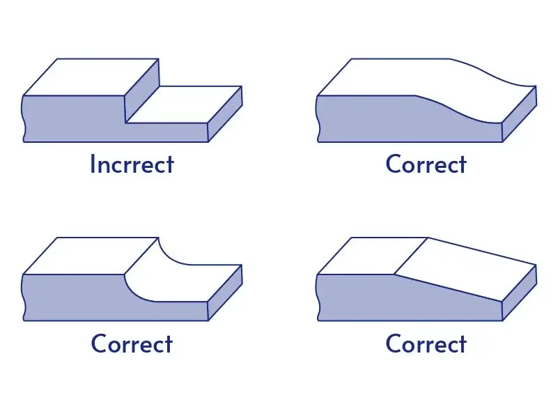
- Implement gradual transitions between different wall thicknesses to reduce defects and internal stresses.
- Avoid areas of concentrated thickness by using hollow structures or reinforcing ribs.
- Design the inner wall slightly thinner than the outer wall to prevent sink marks and dents.
- For unavoidable thick sections, use radii at edges, slight chamfers, or cores.
- Employ geometric features like ribs, curves, and corrugated surfaces to enhance stiffness without increasing overall thickness.
2. Draft Angle – Plastic Part Design Guidelines
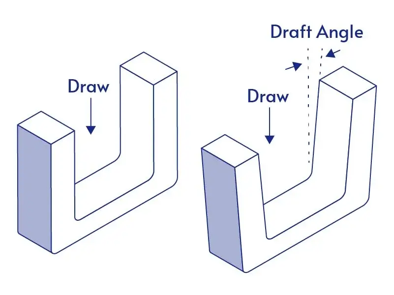
Plastic Part Design Guideline: Draft angles are a critical design feature. Draft angles allow plastic parts to be easily released from the mold when ejector pins are used after cooling.
The Purpose of Draft Angles Design:
Facilitate Part Removal: The primary purpose of draft angles is to allow for easier ejection of the molded part from the mold cavity. The tapered surfaces reduce friction and suction between the part and mold walls during ejection.
Prevent Part Damage: Proper draft angles help prevent scratching, scuffing, and other surface defects that can occur when parts stick to the mold during ejection.
Improve part quality: By enabling smoother ejection, draft angles help maintain dimensional accuracy and surface finish of the molded parts.
Extend Mold Life: Reducing ejection forces through proper draft angles decreases wear on mold components, extending the overall life of the mold.
Increase Production Efficiency: Easier part removal allows for faster cycle times and fewer rejected parts.
Recommended Draft Angle Values:
- General recommendations:
- Minimum: 0.5° on all vertical faces
- Typical range: 1° to 3°
3. Corner and Edge Design
When you design plastic part for injectin molding, the designer should avoid sharp corners and edges. Because The sharp corners impede plastic melt flow, causing flaws in parts. Sharp corners impede plastic melt flow, causing flaws in parts. Stress concentration easily occurs at sharp corners, reducing part strength. Sharp corners create high levels of molded-in stress during cooling. Sharp edges are difficult to maintain during molding and can tear or chip during part removal.
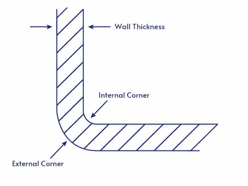
Recommended radii for internal and external corners:
- General Recommendation: The inside radius should be 0.5T and the outside should be 1.5T, where T is the wall thickness.
- For injection molded parts, inside radius of half the nominal wall thickness and an outside radius of 1.5 times the nominal wall thickness is recommended.
- A minimum radius of 0.010 inches (0.25 mm) is suggested for edges that cannot be completely rounded.
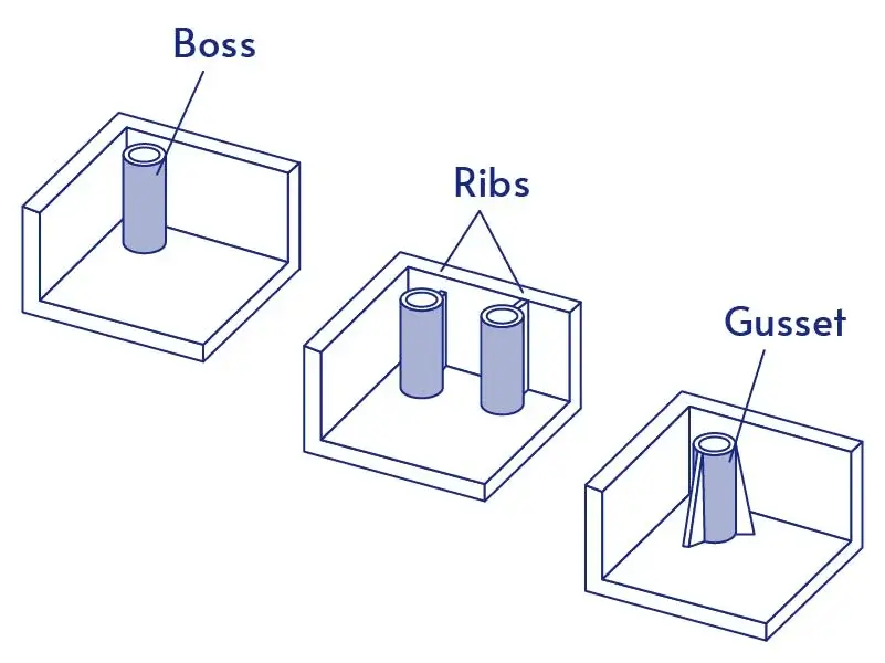
4. Rib and Boss Design
Ribs and bosses are important structural features in plastic parts design.
Ribs are thin, wall-like projections that extend from the main body of a plastic part. They increase part stiffness and strength without significantly increasing overall wall thickness, provide support for other features, and guide material flow during the molding process.
Bosses are cylindrical protrusions or hollow columns in a plastic part. They are creating mounting points for screws or other fasteners. Providing locations for assembly with other components and acting as spacers or standoffs.
Rib Design Guidelines:
- Rib thickness should be 50-60% of the nominal wall thickness. For glossy materials, reduce to 40% of wall thickness to avoid sink marks.
- Maximum rib height should be 2.5-3 times the nominal wall thickness. Taller ribs may be difficult to fill completely.
- Minimum spacing between ribs should be 2-3 times the nominal wall thickness.
- Increase the number of ribs rather than height to improve stiffness.
- Include 0.5° to 1.5° draft angle on ribs for easy ejection.
- Use radii of 0.25-0.5 times the nominal wall thickness at rib bases.
Boss Design Principles:
- Boss wall thickness should be 60-80% of the nominal part wall thickness.
- Maximum boss height should be 2-3 times the boss diameter.
- Include 0.5° to 2° draft angle on boss walls.
- Add gussets or support ribs to tall bosses for stability.
- Core out thick bosses to reduce material and cycle time.
5. Surface Finish and Texture
Common texturing methods include bead blasting, etching, and applying patterns like leather grains or geometric designs.
plastic part design for injection molding suface finsh and texture are equally important.
Guidelines for Applying Textures:
- Consider texture early in the design plastic process, as it affects material selection, tooling, and other plastic parts process decisions.
- Texture depth should be considered when determining draft angles. Deeper textures require larger draft angles for proper part removal.
- Material properties affect how well textures are reproduced. Harder materials and darker colors tend to show textures more prominently.
6. Multiple Assembly Methods Design Strategies
When designing plastic parts for assembly, there are several key principles to consider:
Snap-fit Design Principles:
- Choose materials with sufficient flexibility and strength, like polypropylene or ABS.
- Cantilever beam thickness should be 50-60% of the nominal wall thickness.
- Maximum beam height should be 2.5-3 times the nominal wall thickness. Include a 0.5-1.5° draft angle on snap features for easy ejection.
- Add fillets at the base of cantilever beams (radius 0.5x beam thickness). Taper the beam cross-section to distribute stress evenly.
- Design for 2-3° of interference between mating parts.
- Include lead-in angles of 15-30° to guide assembly.
- Consider assembly forces and directions.

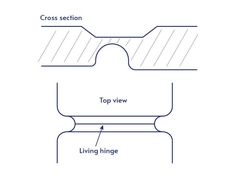
Living hinge design principles:
Living hinges plastic part design for injection molding should be using flexible materials such as polypropylene or polyethylene. For most applications, the thickness of the hinge typically ranges from 0.2 to 0.3 millimeters. It is important to ensure that the width of the hinge is at least four times the thickness of the material. When creating bends in the hinge, use a radius that is 1.5 to 2 times the material thickness. Finally, for optimal performance, align the hinge parallel to the direction of the mold flow during manufacturing.
Considerations for inserts and fasteners:
When designing bosses for inserts and fasteners, the wall thickness should be between 60% and 80% of the nominal part wall thickness. The maximum height of the boss should not exceed 2 to 3 times its diameter. It’s important to include a draft angle of 0.5 to 2 degrees on the boss walls to facilitate part removal from the mold. When selecting inserts, choose those that are compatible with the plastic material being used. Additionally, consider the differences in thermal expansion between the insert and the plastic to prevent issues during temperature changes.