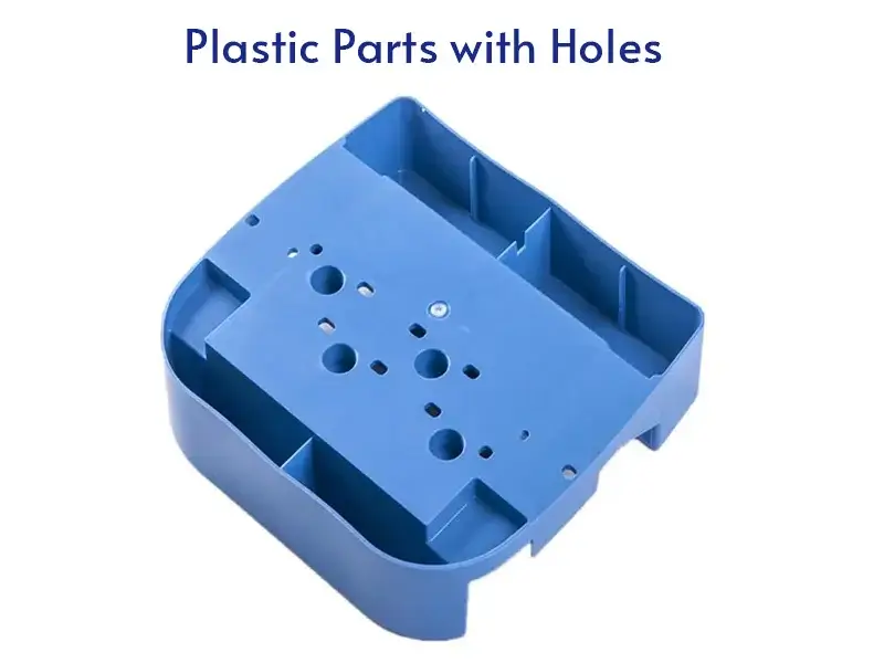
Plastic parts with holes are a type of plastic parts structure. In hole in plastic parts design, it must be a straight hole, that is, its cross sections must be parallel. Plastic parts holes play a crucial role in design of plastic components. These parts are created through different manufacturing processes. The general minimum hole diameter that can be reliably produced by injection molding is around 0.5 mm (0.020 inches). In this post, we will explore the plastic part hole design, types, benefits, applications, and manufacturing processes.
Types of Holes in Plastic Parts
Plastic parts can feature various types of holes, each serving specific purposes in design and functionality. Here are the primary types of holes commonly found in plastic parts:
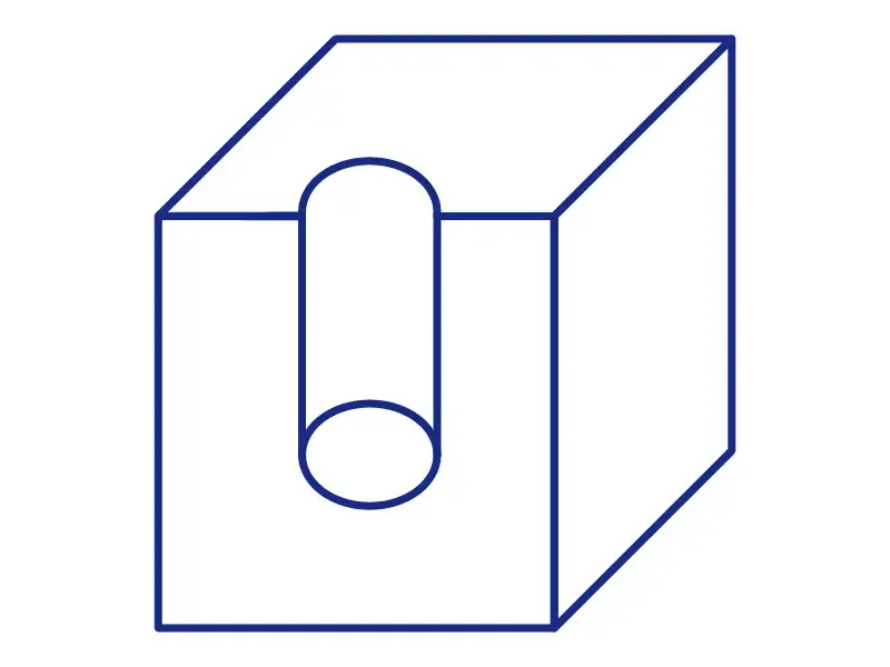
1. Through Hole in Plastic Injection Molding
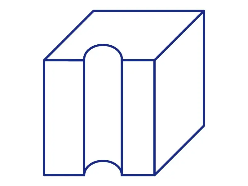
Through holes are holes that pass completely through the part. They are easier to manufacture and are commonly used in assembly processes such as fasteners like screws, bolts, and rivets that need to pass through the part and be secured on the other side. These holes can be formed using cores fixed in both the movable and fixed parts of the mold, which helps maintain structural integrity and minimize deformation.
When design through holes, must be ensured proper alignment with corresponding holes in mating parts, and consider the impact on the structural integrity of the part.
2. Blind Hole in Plastic Injection Molding
Blind holes do not go all the way through the part. They are created by insert cores that are only supported at one end, making them more prone to deformation under the pressure of molten plastic. Blind holes often used for inserts, tapped holes for screws, or as mounting points where a through hole is not necessary or desirable. The depth of blind holes should generally not exceed twice their diameter to avoid structural issues.
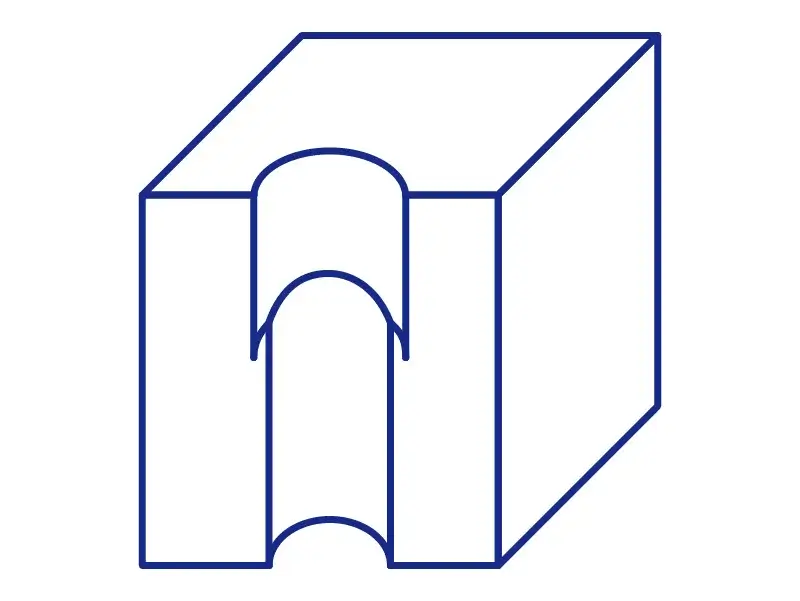
3. Stepped Hole in Plastic Injection Molding
Stepped holes have varying diameters along their depth, often used to accommodate different components or to provide additional structural support. These holes can be more complex to design and manufacture but offer enhanced functionality.
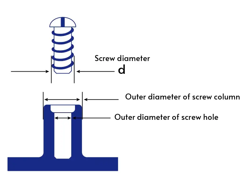
4. Screwed Holes/Tapped Holes
Screwed holes also named tapped holes, are threaded to allow for the insertion of screws or bolts. Screwed holes are frequently used in assemblies where parts need to be disassembled and reassembled, providing strong and reusable connections.These holes require precise design to ensure proper threading and to avoid generating internal stresses that can weaken the part.
5. Irregular Shaped Holes/ Special Shapes and Patterns
Those holes that are not standard circular shapes, including slots, keyholes, or custom geometries. They are used for specialized functions such as keying features for alignment, accommodating irregularly shaped components, or creating specific flow paths for fluids or gases.
The complexity of the hole shape may impact the manufacturability and mold design. Ensuring consistent dimensions and smooth transitions is critical to avoid stress concentrations and weak points.

Countersunk Holes and Counterbore Holes
6. Countersunk Holes
Countersunk holes with a conical top section allow flat-headed screws to sit flush with or below the surface. They are used when a smooth surface finish is needed, often in assemblies where aesthetics or avoiding protrusions is important.
The angle of the countersink should match the screw head, and adequate material around the countersink is necessary to maintain strength.
7. Counterbore Holes
Counterbore holes with a cylindrical recess at the top allow the head of a bolt or screw to sit flush with or below the surface.They are common used in mechanical assemblies where bolt heads need to be hidden or recessed.
The diameter and depth of the counterbore must be designed to accommodate the specific fastener, ensuring there is enough surrounding material to maintain part integrity.
8. Side Hole in Plastic Injection Molding
Side holes are oriented perpendicular to the main axis of the part and often require additional mold components like side cores or sliders. These holes can significantly increase mold complexity and cost.
Optimize the Design of Plastic Parts with Holes to End Stress Cracking and Assembly Failure!
Manufacturing Process and Considerations
Designing holes in plastic parts involves addressing various manufacturing aspects to ensure the parts are produced efficiently and with high quality.
Injection Molding Process for Plastic Parts Holes
The presence of holes can significantly influence the design and complexity of the mold. They can be formed directly during molding by using core pins or inserts in the mold design. This allows for the creation of various types of holes, including through holes, blind holes, and threaded holes. The additional mold components such as core pins or inserts, can increase mold cost.
Ejection Challenges and Solutions:
During the ejection process, the parts with holes have the potential for deformation or damage. Design the ejection system carefully, using techniques such as undercuts, lifters, or ejector pins positioned to avoid placing stress on critical areas around the holes. Additionally, consider using draft angles to facilitate smooth ejection.
Post-Processing Hole Creation
For some applications or materials, holes may need to be created or refined after the initial manufacturing process. Common post-processing methods include:
Drilling: Precision drilling can be used to create holes in specific locations after molding or printing. This is often used for creating smaller holes or when tight tolerances are required.
Punching: For thinner plastic parts, punching can be an efficient method to create holes, especially in high-volume production.
CNC Machining: Computer Numerical Control (CNC) machining can be used to create precise holes in plastic parts, offering flexibility in hole size, shape, and placement.
Laser Cutting: For certain plastics, laser cutting can be used to create precise holes, especially in sheet materials.
Design Considerations for Plastic Parts with Holes
When designing plastic parts with holes, several key factors must be considered to ensure optimal functionality, manufacturability, and structural integrity. Here are the main design considerations:
Hole Placement and Sizing
Proper hole placement and sizing are crucial for part functionality and manufacturability. Keep holes at least one diameter away from edges and other holes to maintain structural integrity. For blind holes, limit hole depth to 2-3 times the diameter to ensure proper filling and avoid sink marks. The minimum hole diameter should typically be no less than 0.5mm for most injection molding processes. For through holes, maintain an aspect ratio (depth to diameter) of no more than 3:1 to ensure proper filling and ejection.
Wall Thickness and Structural Integrity
Wall thickness affects both the structural integrity of the part and its manufacturability. Aim for uniform wall thickness to prevent warping and sink marks. Generally, wall thickness should be between 1.2mm to 3.5mm for most applications. Use ribs and gussets to reinforce areas around holes instead of increasing overall wall thickness. Use gradual transitions in wall thickness to avoid stress concentrations.
Draft Angles and Ejection Concerns
Draft angles and proper ejection design are crucial for successful part removal from the mold. To facilitate part ejection, include a minimum draft angle of 0.5° to 2° on all vertical surfaces, including hole walls.
Position ejector pins strategically, avoiding placement directly on or near holes to prevent deformation. Avoid undercuts in hole design as they can complicate part ejection. If necessary, consider side-action cores or two-part molds. Align holes with the mold opening direction when possible to simplify manufacturing and improve hole quality.
Additional Considerations
Tolerances: Specify appropriate tolerances based on the part’s functional requirements and manufacturing capabilities.
Surface Finish: Consider the required surface finish inside the holes and how it affects the manufacturing process.
Assembly Requirements: Design holes with assembly in mind, considering factors like clearance for fasteners or mating parts.
Stress Distribution: Use Finite Element Analysis (FEA) to optimize hole placement and sizing for even stress distribution.
Conclusion
Designing plastic parts with holes is a critical aspect of product development that requires careful consideration of various factors to ensure functionality, manufacturability, and structural integrity. As manufacturing technologies advance, plastic parts with holes will continue to evolve, offering new possibilities for product design and functionality across various industries. By understanding the importance of holes in plastic components and following best practices, designers can create parts that meet performance requirements and are cost-effective to produce.


